
In 2003, I installed a Xantrex Freedom 458 2000 Watt inverter/charger, a Link 1000 monitor/controller, and a 440 Amp Hour battery bank in our 2002 Bigfoot 25C10.6 camper. The inverter and batteries were formerly installed in our old camper, a 2000 Palomino Maverick 8801.
The inverter provides enough power to power our microwave, drip coffee maker and toaster when we are boondocking. It also comes in handy for using the microwave to reheat leftovers for lunch when we are on the road. The charger portion is a computer controlled 3-stage 100 Amp charger that takes very good care of our batteries, and recharges them very quickly.
I hope the description of my install helps you with yours, or at least gives you an idea to improve upon. Please understand that this description documents howI did it and is not intended to be a "How To" document for others. Email me if you have any questions.
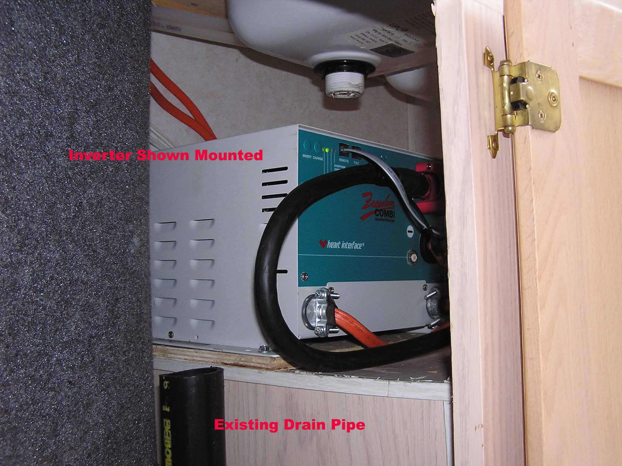
Our Bigfoot does not have a generator, so I installed the batteries in the generator compartment and the inverter under the kitchen sink. The installation required the following major steps:
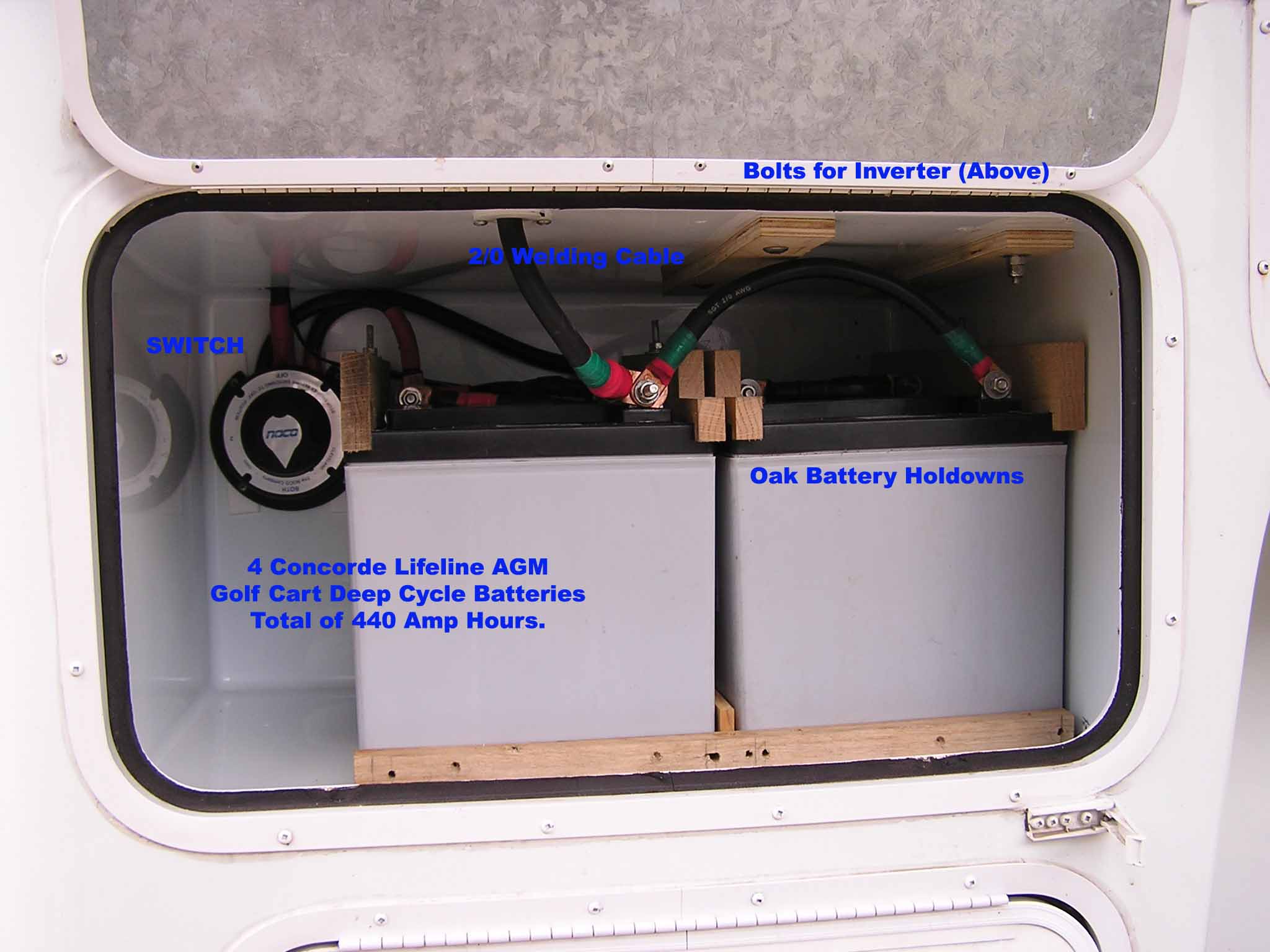
1. Install a secure battery mount in the generator compartment. Along with the batteries, I installed a battery selector switch that is mainly used as a battery disconnect. It can also select between either or both of the two 220AH battery banks. Normally, I use both banks in parallel for best performance.
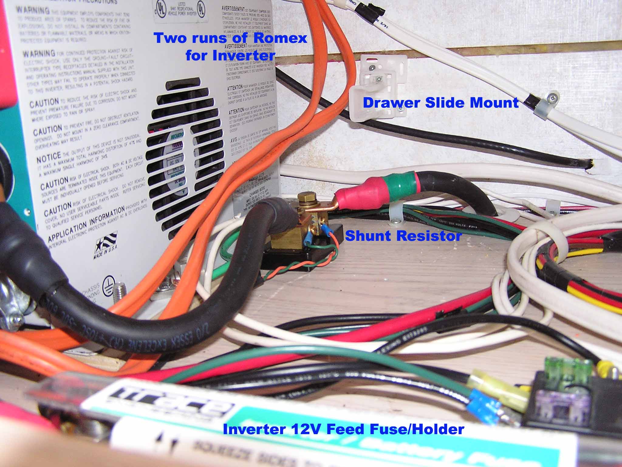
2. Two runs of 10/3 Romex between the converter/breaker box to the area under the sink.
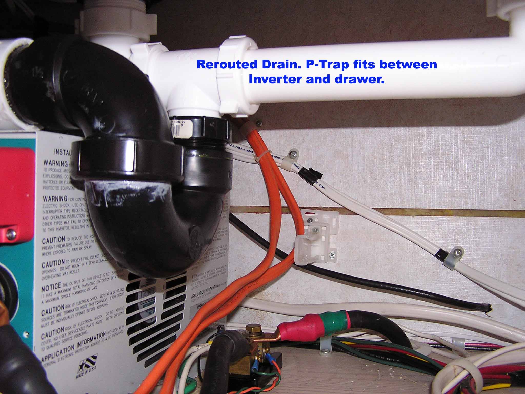
3. Mounting the inverter under the sink also required rerouting of the sink drain in the undersink area. The 300 Amp fuse and shunt resistor for the Link 1000 are also installed under the drawer in this area.
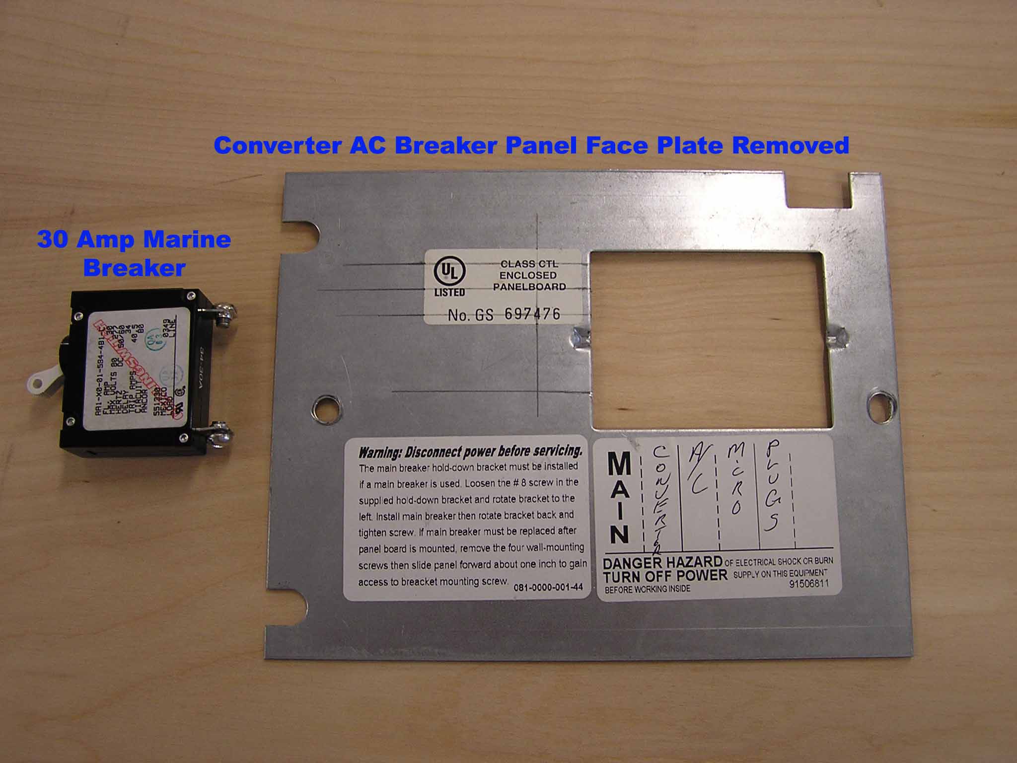
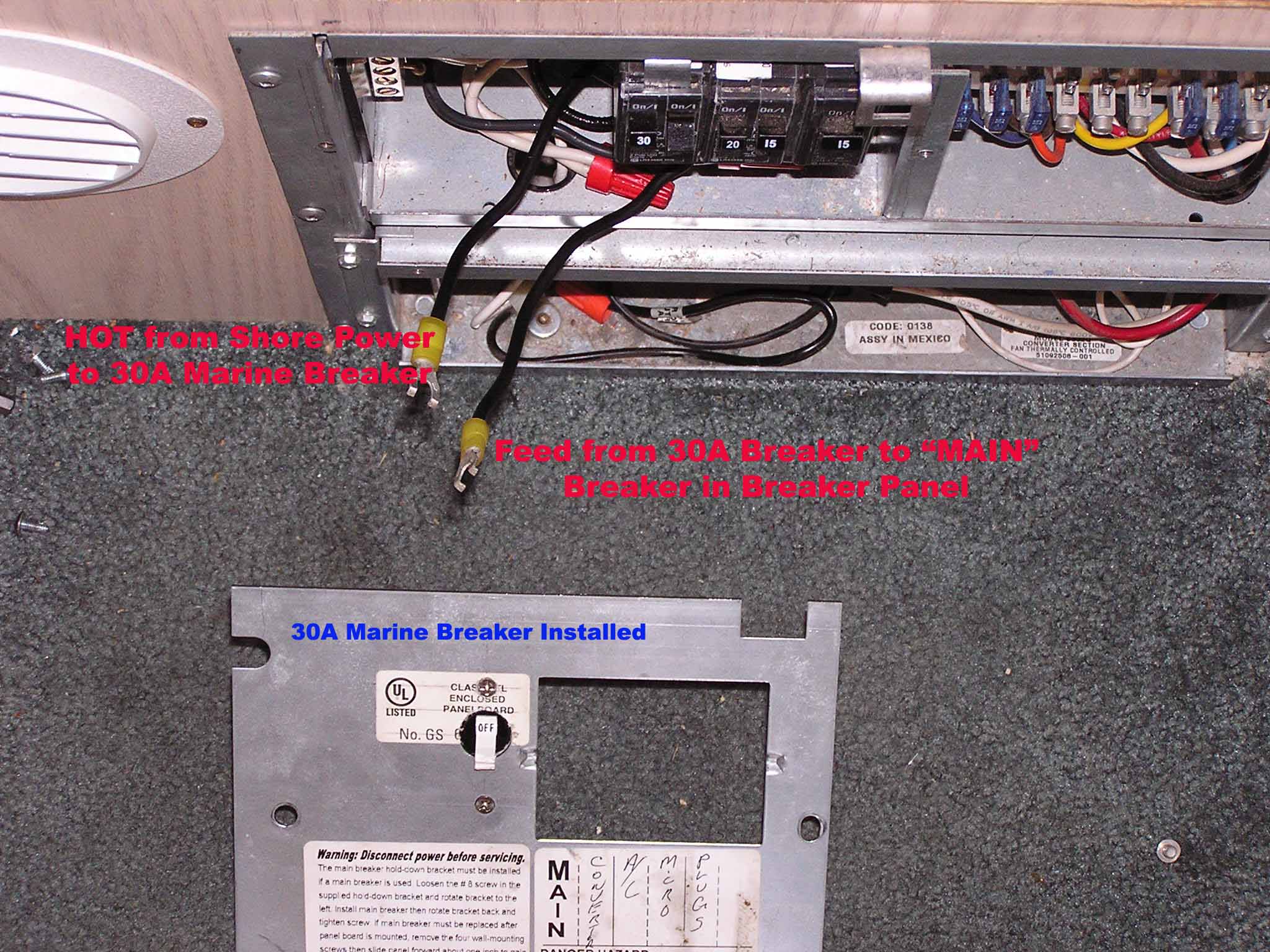
4. Addition of a 30 Amp marine breaker/switch to the existing breaker panel.
5. Installation of the Link 1000.
The sections below describe the installation in our Bigfoot 25C10.6. There is also a detailed description of my previous installation in our old Palomino Maverick 8801 here: Palomino 8801 Installation. There are better pix of the battery holdowns there, as well as a description of how I built a split shore/inverter breaker box.
Battery Mount
The batteries sit on a 1/2" piece of plywood that is bolted to the floor of the generator compartment. The carriage bolts used extend into the normal battery compartment below. There are oak strips screwed to the plywood to keep the bottoms of the batteries separated. I also fabricated some oak strips on my bandsaw to use as battery holdowns and to keep the tops separated. The batteries are arranged as a parallel pair of two batteries in series. The positive battery cable of each bank run to the battery selector switch in the compartment. A plus and minus cable run up through the top of the generator compartment to the fuse and shunt resistor. This allows for an extremely short run from the batteries to the inverter which is very good. All cables are 2/0 welding cables. Welding cables are much more flexible than battery cables.

Romex
I ran two runs of Romex between the inverter and the breaker box. One brings shore power to the inverter/charger and the other returns power to the breaker box. There is no direct connection between shore power and the breaker box. The breaker box is either powered by shore power or inverter power via the inverter's built in automatic transfer switch.
Note that I could have gotten by with a single run of Romex as there is already a factory installed run between the shore power compartment and the generator compartment, but I decided to leave that run alone in case I, (or the next owner) ever decide to install a generator.
Inverter Mounting
In order to mount the inverter under the sink, I temporarily removed the undersink drawer and the left drawer slide for better access. Then I rerouted the drain from the left half of the kitchen sink so it jogged to the right instead of dropping straight down as it came from the factory. Then I routed the drain so it would go over over the top of the inverter and then join back up to the factory drain.
The inverter is bolted to the floor of the undersink area through the top of the generator compartment. The shunt resistor for the Link 1000 and the 300 Amp fuse between the batteries and inverter/charger are also mounted to the floor underneath the drawer.

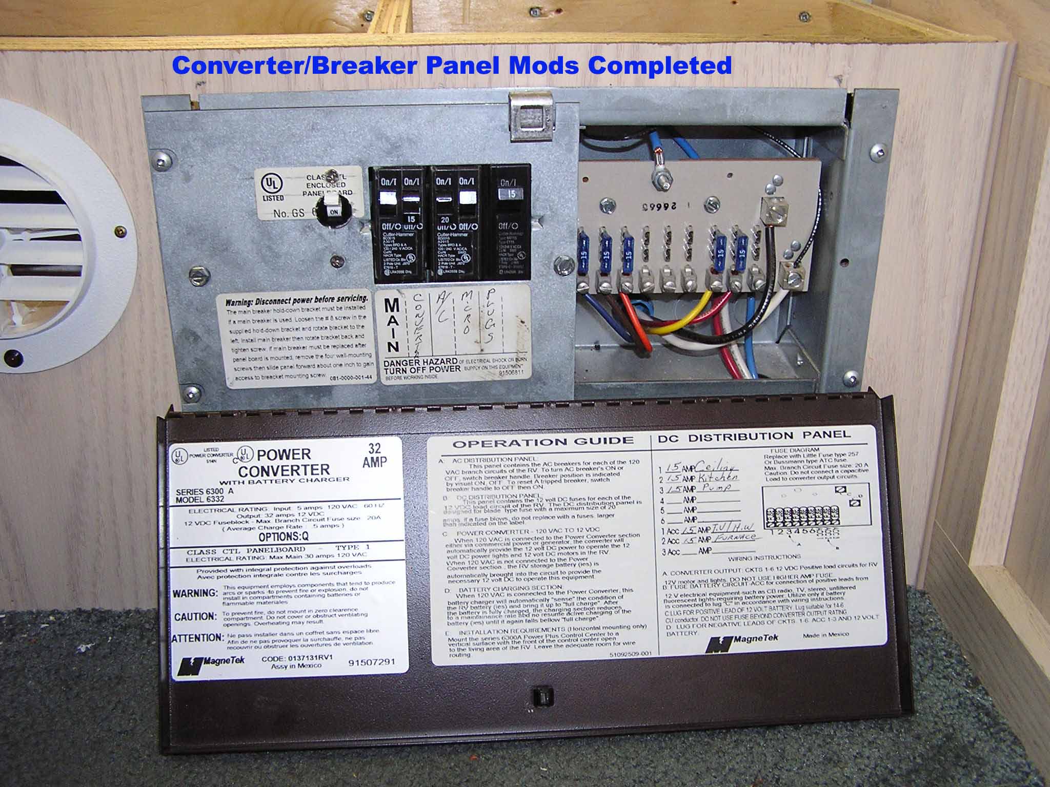
Converter/Breaker Box Modifications
I chose to make the mods to the breaker box fairly simple. All of the existing breakers are fed from either the inverter or shore power. Although this makes installation a little simpler, it does require me to remember to switch off things I don't want to be powered by the inverter. The main thing here is to remember to switch the refrigerator from auto to gas when boondocking. If left on auto, the refrigerator will run off the inverter when shore power is not present and the inverter is turned on to power other AC devices.
The other modification to the breaker box is the addition of a marine 30 Amp breaker/switch. This is used as the shore power disconnect instead of the breaker normally used for this in the breaker box.
I also physically disconnected the converter. Since the Freedom 458 has a built in automatic 3-stage 100 Amp battery charger, the converter is neither desired nor needed. Normally the converter is fed from a breaker and leaving this breaker off will disable the converter. I just took this extra precaution to avoid accidentally flipping the converter on. If I ever do need the converter in an emergency, it is easily reconnected.
Link 1000 Monitor/Controller
The Link 1000 is a great unit that acts as a "gas gauge" for the battery bank as well as providing some very useful information about battery condition, discharge rate, etc. Installation is fairly straightforward and it is mounted just under the countertop lip in the kitchen cabinet near the inverter/charger.